|
|
||
|
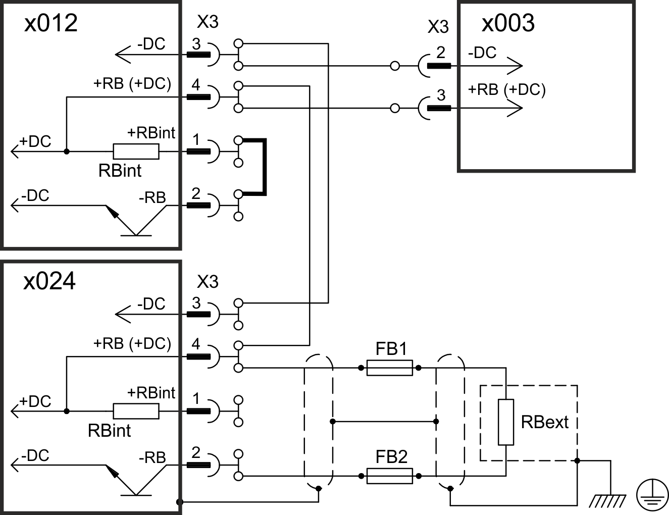
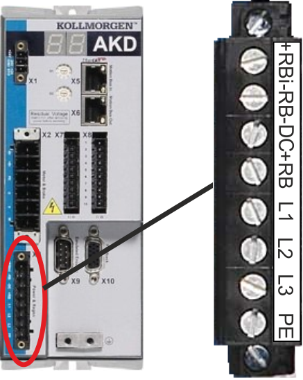
Pin |
Signal |
Description |
|
2 |
-DC |
DC-Link Bus negative |
|
3 |
+DC (+RB) |
DC-Link Bus positive |
|
01206 (X3) |
||
|
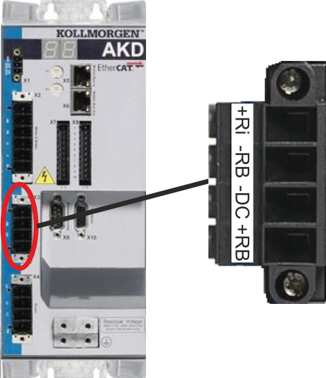
Pin |
Signal |
Description |
|
3 |
-DC |
DC-Link Bus negative |
|
4 |
+DC (+RB) |
DC-Link Bus positive |
|
02406 |
||
|
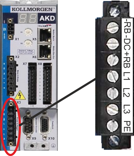
Pin |
Signal |
Description |
|
3 |
-DC |
DC-Link Bus negative |
|
4 |
+DC (+RB) |
DC-Link Bus positive |
|
04807 (X14) |
||
|
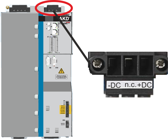
Pin |
Signal |
Description |
|
1 |
-DC |
DC-Link Bus negative |
|
2 |
n.c. |
not connected |
|
3 |
+DC |
DC-Link Bus positive |
NOTE: Should be connected in parallel only with 048 drives.